DTMF Controlled Robot without Microcontroller
DTMF Based Robotic Veicle Circuit Principle:
DTMF based robotic vehicle circuit consists of DTMF decoder IC, driver IC l293D IC and motors.
DTMF decoder IC used is HT9107B. It has 18 pins. Tone from DTMF encoder is given to the DTMF decoder IC. The decoder IC internally, consists of operational amplifier whose output is given to pre filters to separate low and high frequencies. Then it is passed to code detector circuit and it decodes the incoming tone into 4bits of binary data. This data at the output is directly given to the driver IC to drive the two motors. These motors rotate according to the decoded output.
Also Read the Related Post: Simple Line Follower Robot using Microcontroller
If the button pressed from mobile is ‘1’, it gives a decoded output of ‘0001’. Thus motor connected to the first two pins will get 0 volts and second motor will have 5 volts to one pin and 0 volts to the another pin. Thus second motor starts rotating and first motor is off. So, robot moves in one direction either to left or right. If the robot is to rotate forward or backward then the binary value should be either ‘0101’ or ‘1010’.These values indicate that two motors rotates in the same direction i.e. either forward or backward. The following table gives the low frequency, high frequency and binary output value of each button pressed in the keypad.

DTMF Decoded Frequency Output Table
Circuit Diagram of DTMF Controlled Robotic Vehicle without using Microcontroller:
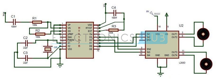
DTMF based Mobile Controlled Robot Circuit Diagram
Circuit Components:
- DTMF Decoder IC (HT9107B)
- Motor Driver IC
- Motors
- Resistors – R1, R2 & R3
- Capacitors – C1 to C4
- Crystal Oscillator
DTMF Controlled Robot Circuit Design:
The main components of the circuit are DTMF decoder IC, motor driver IC and motors. The decoder IC used here is HT9107B IC. The second pin of decoder IC is an inverting pin of the operational amplifier.
Tone is applied to the IC through a series of capacitor and resistor. The output of the Op Amp is feed back through GS pin of the IC. An external crystal is connected to the 7th and 8th pins of the IC.
Motor driver IC used is L293D. It has 16 pins. 2, 7, 10, 15 pins are the inputs of motor driver IC connected from output pins of the decoder IC. The output pins are 3, 6, 11, 14. These pins are connected to the two motors of robotic vehicle. 8th pin is connected to the 5v. Vss is the input voltage with which the motors runs. Motors cannot be driven with 5Vof microcontroller. So, a driver IC is used to amplify this voltage. VSS pin provides this voltage.
Comments
Post a Comment